Section 9.4 Screw Friction
Key Questions
At the end of this chapter you should be able to answer these questions.
- Explain how the right-hand rule relates to the motion and rotation of screws,
- Compute the thread pitch and friction angle for a screw,
- Contrast the different types of screw motion, with and against applied loads, and match the motion cases to their corresponding equation, and
- Describe how a screw and nut move in relatively opposite directions.
A power screw (also sometimes called a lead screw) is another simple machine that is essentially the surface of a wedge wound around a shaft.
A power screw assembly includes a nut that is machined to fit around the screw. There are several ways that a power screw can be used, based upon the movement of the screw and nut.
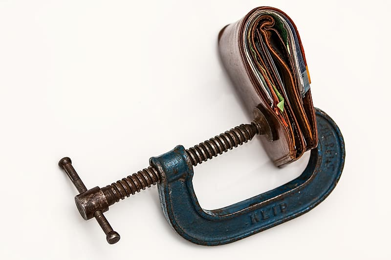
A C-clamp is an example of a screw which rotates and translates through a fixed nut.
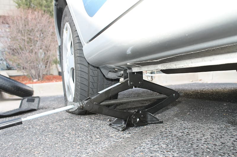
Compare that with with a scissors car jack. Here the screw rotates and the nut (on the far end) translates along the screw. The handle end of the screw acts as a thrust bearing but is not threaded.
In either case, a small moment on the screw can cause enormous forces on the nut, with the added benefit of the force being applied at a precise location as controlled by the screw.
Subsection 9.4.1 Screw motion and the Right-hand-rule
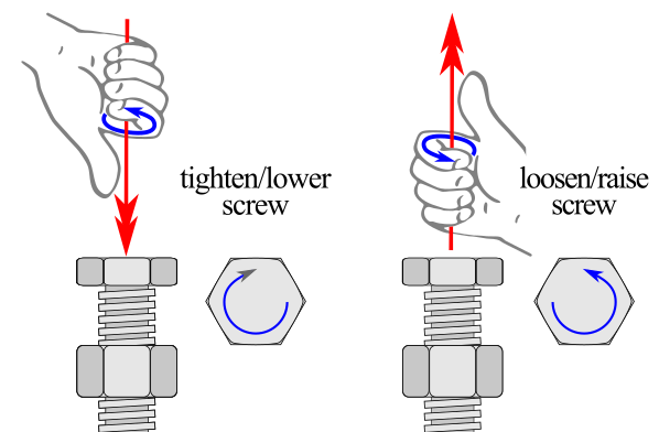
Most screws are right-hand threaded, which means that when you are looking at the head of a screw and rotate the top of the screw to the right, it tightens (commonly taught as “righty-tighty”). Another way to think about the relationship between screw rotation and motion uses the right-hand rule. When you make a thumbs up with your right hand, if you rotate a screw towards your fingertips (clockwise = CW), then the screw will move in the direction of your thumb (as shown in Figure 9.4.4). Of course, the reverse is true as well if you want to loosen the screw from its nut.
Note that there is a small percentage of screws that are left-hand threaded. Their application is often related to:
- machines where the reverse-threading prevents them from loosening gradually under the torque of the moving part (like the left pedal on a bicycle)
- machines where the movement of the screw creates dual motion (like a hand-screw wood clamp)
- situations where you do not want to mix up constituents (like the oxygen and acetylene tanks on a cutting torch)
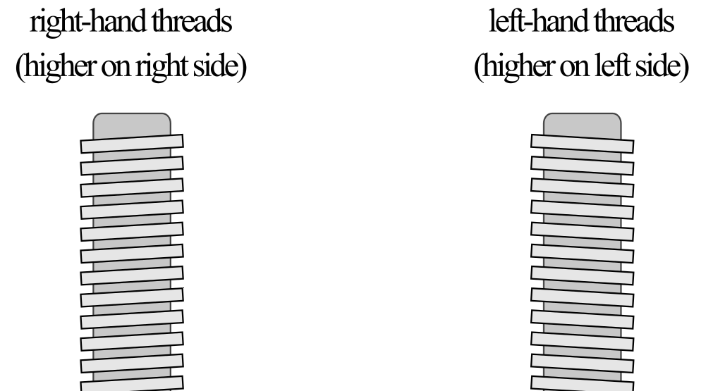
The motion of left-hand screws can either be thought of as opposite the right-hand rule or conforming to the same relationships if you use your left hand.
Subsection 9.4.2 Screw thread properties
For computational simplicity, all screw problems in this course will focus on square-threaded screws. Note that other threading shapes (like Acme or Trapezoidal threads) are also common, but their angled threads increase the computational complexity. The easiest way to analyze a square-thread power screw system is to turn the problem into a two-dimensional problem by "unwrapping" the ramp from around the cylinder of the shaft. We can summarize the geometry of the screw using two values (1) the mean radius of the screw (r) and secondly the lead (l) (also called the pitch), which is the distance between two adjacent threads. Alternately, you can compute the lead by computing the inverse of the threads-per-inch or centimeter. With a single thread design, this will also be the number of times the thread wraps around the screw in one inch/centimeter.
To visualize these terms, we can imagine unwrapping a thread from around the screw, as seen below.
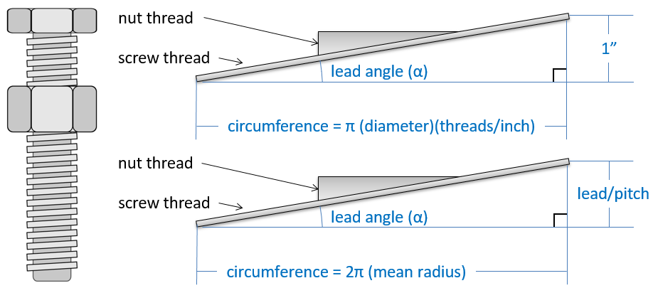
Using the right triangle shown in Figure 9.4.6, we see that the thread pitch \(\alpha\) (also known as the lead angle or helix angle) is the inverse tangent of the ratio of the lead over the circumference
Subsection 9.4.3 Moments to reach impending motion
The focus of all screw problems covered by this book is to find the required rotational moment to push a screw to impending motion. As impending motion is the threshold between the system holding still and moving, your knowledge of the moments required at impending motion allows you to interpret what happens to the screw system in static-but-not-impending conditions as well.
Since all friction is impending, we will use the coefficient of static friction \(\mu_\text{s} \)and the related friction angle \(\phi_\text{s}\text{.}\) Recall from earlier in this chapter, that the friction angle \(\phi_\text{s}\) can be related directly to \(\mu_\text{s}\) the by the equation:
We now have the tools assembled to derive the relationship between a screw's geometry and applied loads.
Subsection 9.4.4 Screws where the applied force opposes impending motion
The first scenario we will examine is the amount of moment \(M\) required to raise a screw to impending motion against the applied force \(W\) (Figure 9.4.7). To eliminate any references to the orientation of the screw and force (like upward, downward, left, or right), this type of motion will be described as “the applied force opposes impending motion.” This case occurs any time you are applying a force to an object with a screw (like tightening a clamp).
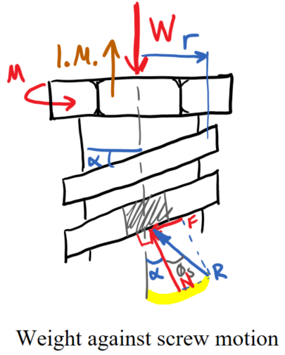
For screw analysis, it is often easiest to express the friction force \(\vec{F}\) and normal force \(\vec{N}\) as the friction resultant \(\vec{R}\) and the friction angle \(\phi_\text{s}\text{.}\) Recall that the friction force \(\vec{F}\) direction always opposes the impending motion of the point of contact – in this case, the screw threads. Also, the thread angle \(\alpha\) determines the angle of the normal force \(\vec{N}\) from the centerline of the screw. Finally, the friction angle \(\phi_\text{s}\) is the angle between the friction resultant force \(\vec{R}\) and the normal force \(\vec{N}\text{.}\)
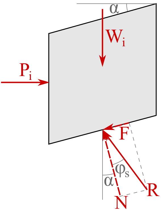
Summing the forces in the \(x\) and \(y\) directions for the FBD in Figure 9.4.8 yields:
By summing the forces across all elements of one wrap of the screw we find:
We next need to reduce these two equations to a single equation and also eliminate the difficulty to quantify \(\Sigma R\) term. Thus we solve both equations for \(\Sigma R\text{.}\)
Finally, set these to equations equal to each other and solve for the moment M.
Where: \(M\) is the moment required to raise the screw to impending motion, \(W\) is the force load on the screw, \(r\) is the mean radius of the screw, \(\phi_\text{s}\) is the screw friction angle, and \(\alpha\) is the screw thread pitch.
Practically, you can interpret from this equation that the moment to move a screw against an applied force must overcome the screw friction (represented by \(\phi_\text{s}\)) and also the component of the weight on the screw (represented by \(\alpha\)).
Subsection 9.4.5 Screws where the applied force supports impending motion
When the impending motion of the screw is in the direction of the applied force, we can also state that the “applied force supports impending motion.” This case occurs any time you remove a force held by a screw (like loosening a screw clamp). This motion case is a bit more complicated than the force opposing impending motion, as there are three different cases determined by the relative magnitude of the friction angle \(\phi_\text{s}\) and the thread angle \(\alpha\text{.}\) The basic derivation and variables in the case-specific equations below are quite similar to the derivation for (9.4.1), but use subtly different FBDs (see Figure 9.4.9 below).
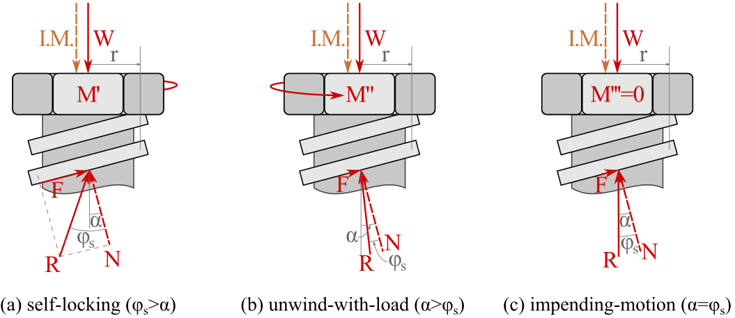
Self-locking screw\((\phi_\text{s} \gt \alpha)\) Self-locking screws are the typical type of screws that you will encounter in mechanical systems as they are highly predictable. They have sufficient friction available to hold their applied load even with no moment applied. Thus, they would be safely carrying the load in a static-but-not impending condition until you wish to overcome the excess friction by using a moment \(M’\) to push them to impending motion.
Unwind-with-load screw\((\phi_\text{s} \lt \alpha)\) - As its name implies, an unwind-under-load screw will start turning unless a moment \(M’’\) is applied to keep the screw at (or beyond) impending motion. Note that the moment to push a self-locking screw to impending motion \(M’\) is in the opposite direction as the moment to keep unwind-under-load screws at impending motion \(M’’\text{,}\) as \(M’’\) is in the same direction as the moment to loosen (or raise) a screw. These unwind-with-load screws are not often found in mechanical systems, except for in dynamic motion control systems, where the screw is used to slow down motion. To be designed in an unwind-with-load condition, a screw must have a quite steep thread angle \(\alpha\) and minimal friction between the threads and nut, which reduces \(\phi_\text{s}\text{.}\)
Impending-motion screw\((\phi_\text{s}=\alpha)\) - As the derived equations for all three unwind-with-load screw cases push the screw to impending motion if a screw is already at impending motion, it requires no applied moment. Note that this case is mechanically unstable. If the load increases, the screw will begin to unwind-under-load, whereas if the load decreases, the screw will become self-locking.
The concept of an applied force in the direction of impending motion works for either (1) a force applied in the impending motion direction of a screw, or (2) a force applied to the impending motion direction of a nut. The first case holds in the derivation and Figure 9.4.9 above, and the second could be seen in an example of a screw jack on a car that has a rotating but non-translating screw, plus a non-rotating but translating nut.
For an alternate derivation of the screw equations based upon wedges, please see the appendix.
Thinking Deeper: Absolute vs. Relative Motion of Screw and Nut.
Thinking Deeper - Absolute vs. Relative Motion of Screw and Nut [box]
As we have seen, screws typically rotate but can be designed to for the screw or nut to translate depending on the intended use. To better understand the use of screws and nuts, it is valuable to learn about the differences between absolute and relative motion. Absolute motion is the motion you observe from a stationary reference point. The speed of a car or the velocity of the wind are all typically measured from an absolute (or non-moving) reference frame. When we choose to measure the same terms from a moving reference frame, they are considered relative motion terms. For example, the velocity of a car relative to a moving train is a relative velocity term. We typically label absolute velocity with a single variable subscript, like the velocity of car \(C\) could be written \(\vec{v_C}\text{.}\) Relative velocities we write with a slash between the two moving objects, like a fraction in the subscript. So, the velocity of the car \(C\) relative to the moving train \(T\) is written \(\vec{v_{C/T}}\text{.}\) The relationship between the absolute and relative velocities of two particles can be written as:
The relative motion of a fixed object can also be measured from the reference frame of a moving object. Thus, we find that the stop sign’s relative velocity with respect to a moving car is equal and opposite to the car’s absolute velocity.
but since the velocity of the stop sign is zero,
The same concept can be applied to screws and nuts. In a system where a screw both translates and rotates, but the nut is stationary, you would find that the relative translation direction of the nut is equal and opposite to the absolute translation of the screw. We will use relative motion for this and other friction topics in Statics also heavily in Dynamics.