Section 5.2 Degrees of Freedom
Degrees of freedom refers to the number of independent parameters or values required to specify the state of an object, where state for a rigid body refers to its position and orientation in space.
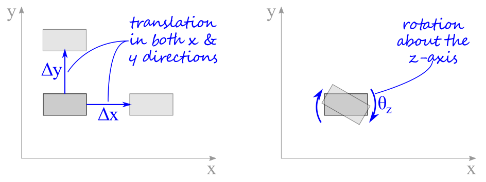
As shown in the figure below, for an object existing in the \(xy\) plane, any translational movement can be represented by changes in the \(x\) and \(y\) coordinates and changes in orientation by angle \theta_z. Therefore, the complete movement of the body can be defined by two translations and one rotation — hence, three degrees of freedom for an object in two-dimensional space.

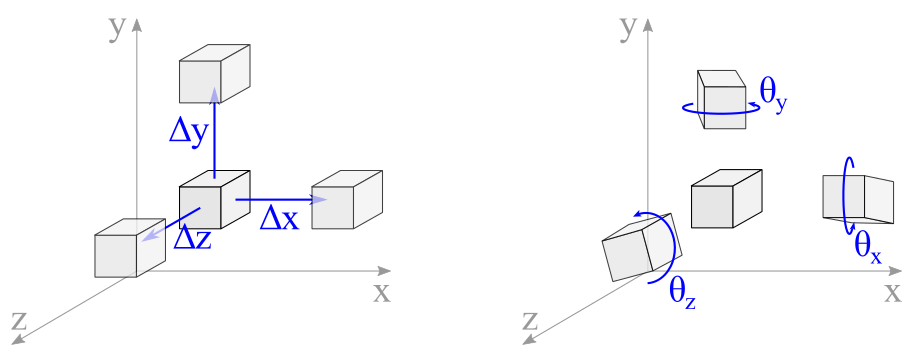
Later in this chapter, we will revisit three-dimensional rigid bodies that can translate in and rotate around all three orthogonal directions. Therefore as shown in Figure 5.2.2, translation can be represented by the distances of \(\Delta x\text{,}\) \(\Delta y\) and \(\Delta z\text{.}\) Rotation of the body can occur around all three axes represented by the angular distances \(\theta_x\text{,}\) \(\theta_y\) and \(\theta_z\text{.}\) The complete movement of the body can be defined by three translations and three rotations — hence, six degrees of freedom from an object in three-dimensional space. Three-dimensional equilibrium of simple structures is found in section.

For a body to be in static equilibrium, all possible movements of the body need to be adequately restrained. If a degree of freedom is not restrained, the body is in an unstable state and is not “static.” Stability is highly desirable for reasons of human safety, and bodies are often restrained by lots of restraints so that if one were to fail, the body would still be stable. If the restraints correctly interpreted, then equal constraints and degrees of freedom create a stable system. If the number of restraints exceeds the number of degrees of freedom, the body is in equilibrium, but you will need more equations than we cover in statics determine their values.
Two-dimensional Free Body Diagram Examples.
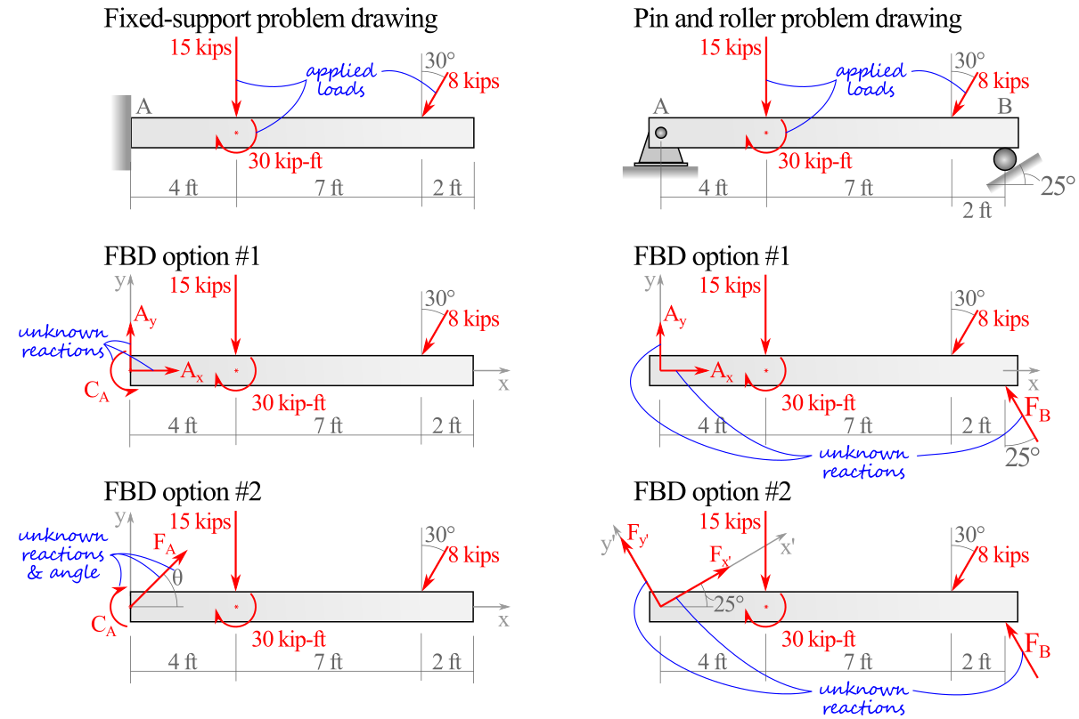
Given that there a handful of options for representing the reaction forces and couple-moments from each support, it turns out there are often a few different equally valid options for drawing free-body diagrams. Figure 5.2.3 demonstrates this flexibility for each of the problem drawings at the top of each column.

On the fixed-support problem drawing on the left side of the figure, notice how the wall at \(A\) prevents the beam from translating up or down, translating left or right, or rotating in the plane of the page. As all three of the two-dimensional motion degrees of freedom are restrained, the beam does not need any additional supports. Conveniently the three unknown reactions also matches the three independent equations of equilibrium which will be discussed later in this chapter.
On the pin and roller problem drawing on the right side of the figure, the pin at \(A\) prevents translation in all directions but allows free rotation. The roller at \(B\) prevents translation in the direction perpendicular to the ground only.