Section 9.5 Flexible Belt Friction
Key Questions
At the end of this chapter you should be able to answer these questions.
- Use the impending motion of the system to determine which side of the belt will have a higher tension
- Compute the contact angle \beta between the belt and pulley or cylinder
- Compute the tension differential on either side of the belt or cylinder for both flat and v-belts
- Compute the maximum torque transfer available from a pulley system
When a belt, rope, or cable is wrapped around an object, there is potential for flexible belt friction. In cases such as a rope over a tree branch being used to lift an object (example in Figure 9.5.1 below), the friction forces resist motion. In other cases, such as a belt-driven system (example in Figure 9.5.2 below), the friction forces help transfer power from one pulley to another pulley.
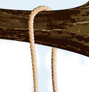
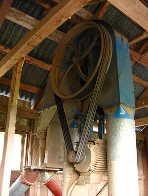
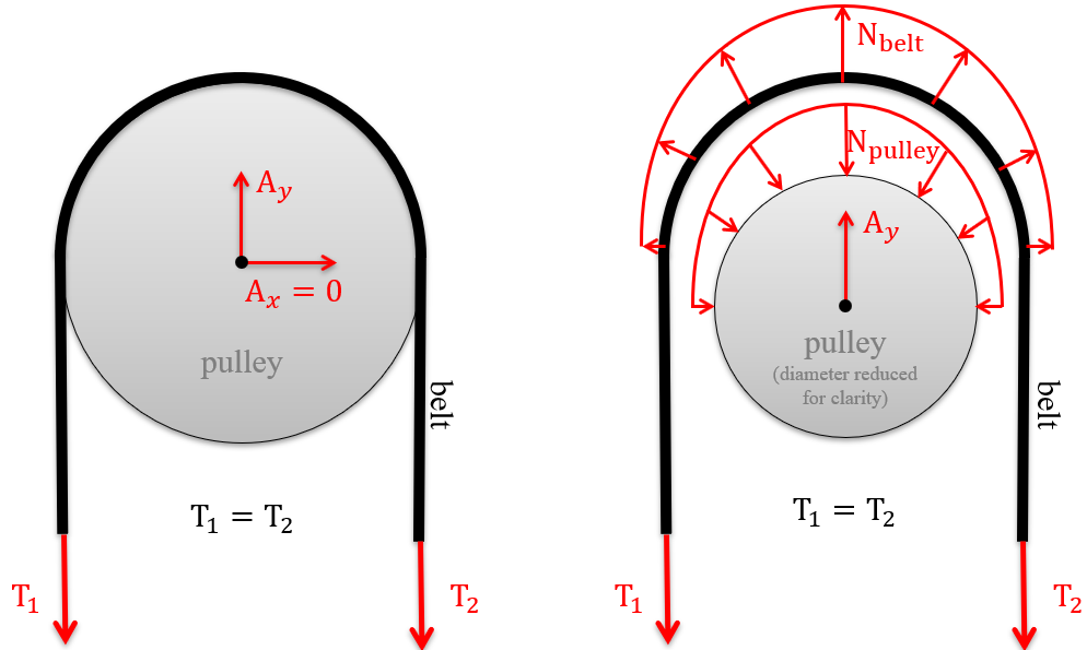
To evaluate flexible belt friction, we start a flat, massless belt passing over a cylindrical surface. If we have an equal tension at each end of the belt, the belt experiences a distributed normal force, which varies as a function of the angle between the contact surface of the belt and the direction the belt tension forces are pulling (Figure 9.5.3).
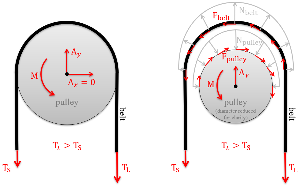
If there were no friction between the belt and cylinder, if we were to increase the tension on one side of the rope, it would begin to slide across the cylinder. However, if friction is available between the rope and the surface, the friction force will oppose the sliding motion (Figure 9.5.4)
Subsection 9.5.1 Friction in Flat Belts
There are two belt shapes discussed in this chapter, flat belts and v-belts (Figure 9.5.5). We start with the analysis of flat belts as they are the simpler of the two.

When analyzing systems with belts, we are usually interested in the range of values for the tension forces where the belt does not slip relative to the surface. Starting with the smaller tension force on one side \(\vec{T}_\text{S}\) we can increase the second tension force \(\vec{T}_\text{L}\) to some maximum value before slipping. For a flat belt, the maximum value for \(\vec{T}_\text{L}\) depends on the magnitude of \(\vec{T}_\text{S}\text{,}\) the static coefficient of friction between the belt and the surface, and the contact angle between the belt and the surface \(\beta\) given in radians.
Subsection 9.5.2 Finding the contact angle \(\beta\)
On flexible belt problems, you need to translate the geometry of the incoming angles of each belt into a contact angle \(\beta\) between the belt and pulley. The easiest way to do this is to create one or more right triangles using the incoming and outgoing belt paths and work through the various complementary angles to transfer the belt geometry into a contact angle \(\beta\) (see example in Figure 9.5.6). There is no simplified rule for transferring cable angles over to the contact angle \(\beta\text{,}\) but in general, extend radial lines from the center of the pulley out to the belt’s tangential lines. Next, create right triangles with each radial line and work to find all the angles which add up to the contact angle \(\beta\text{.}\)
Show β box.Subsection 9.5.3 Determining which belt has the largest tension.
Another challenging step in solving flexible belt friction problems is determining which belt has a larger tension \(\vec{T}_\text{L}\) and which has the smaller tension \(\vec{T}_\text{S}\text{.}\) Unlike guessing the direction of unknown support forces, this is not a decision that you can make incorrectly and later learn of your error with a negative value; hence we will guide you through two ways to make this decision up-front.
Method 1: Draw FBDs and sum tension along the cable.
Draw FBDs and sum tension along the cable. Recall that friction always opposes the motion of the body you are evaluating, thus if you can create an FBD of the cable, you can sum forces along the cable. This equation will verify which tension is larger/smaller.
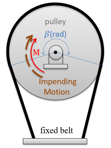
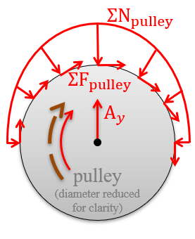
The first FBDshows the following forces acting of the wheel:
- Pin forces (\(O_x\) and \(O_y\)) from the support at the center
- A distributed normal force \(\sigma\vec{N}\) acting radially along the contact surface between the wheel and belt
- A distributed friction force \(\sigma\vec{F}\) acting along the surface of the wheel which is opposing the moment \(M\) and thus the impending motion (I.M.) of the wheel
The second FBDs hows how the contact forces on the wheel are transferred equal and opposite to the belt:
- A distributed normal force \(\sigma\vec{N}\) acting radially along the contact surface between the wheel and belt
- A distributed friction force \(\sigma\vec{F}\) acting along the surface of the belt, which is now opposing the relative impending motion of the belt (which is opposite the absolute impending motion of the wheel).
- Cutting the belt exposes the tension forces within.
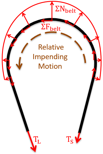
Finally, the forces along the belt are in must be in equilibrium to keep the acceleration equal to zero. We see in this equation that the tension \(T_1\) plus the distributed friction force \(\sigma\vec{F}\) add together to equal \(T_2\text{.}\) Therefore, \(T_2\) must be larger \(T_L\) and \(T_1\) smaller \(T_S\text{.}\)
Method 2: Larger tension is always in the direction of the impending motion of the belt.
Following the logic of Method 1, it turns out that the larger tension \(T_L\) is always in the direction of the impending motion of the belt. It does not matter if the belt motion is relative (like in the example for Method 1 above) or absolute, the larger tension is always in the impending motion of the belt. If you are still learning the differences between relative and absolute motion, see the section above.
There are likely other robust ways to determine the smaller and larger sides of tension in a flexible belt system; make sure you learn a method that works for both potentially moving and also fixed-belt systems.
Subsection 9.5.4 Finding the change in belt tension due to friction
As shown graphically in Figure 9.5.9 above, the friction force engages along the contact surface of the pulley and belt. Zooming in on a single differential element of the belt below in Figure 9.5.10, we will further see the effect of the friction force on the tension within the belt.
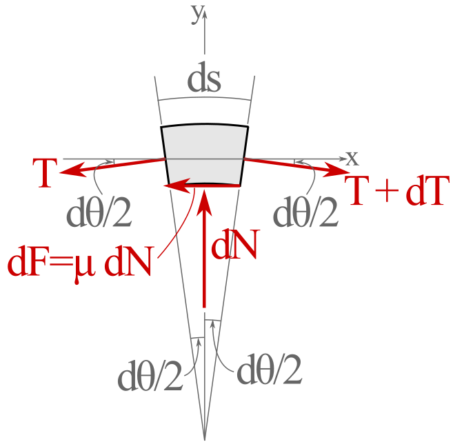
First, sum the forces in the \(x\) the belt element in Figure 9.5.10.
As \(d\theta\) approaches zero, \(\cos (d\theta/2)\rightarrow 1\text{,}\) so in the limit,
Now summing forces in the \(y\) direction,
Where we have used the small angle approximation \(\sin(d\theta/2) \approx d\theta/2\text{.}\) Dropping the second order differential term \(dT\; d\theta\) as negligible, yields
Solving simultaneously by eliminating \(dN\) leaves us with
which we can integrate between \(T_\text{S} \) and \(T_\text{L}\) to find
or by solving for \(T_\text{L}\) we find
where \(T_\text{L}\) is the larger tension pulling on the belt, \(T_S\) is the smaller tension pulling on the belt, \(e\) is the natural log base 2.718, \(\mu\) is the friction coefficient between the belt and pulley, and \(\beta\) is the contact angle between the belt and pulley in radians.
Notice that the differential belt tension is independent of the surface size and shape, provided the belt makes continuous contact.
Subsubsection Friction in V-belts
V-belts fit into a groove on a pulley and thereby increases the normal force of contact with the pulley sides (see Figure 9.5.11 below). This increase in normal force sequentially increases the contact friction. The belt must only contact the sides and not the groove base to maintain this friction advantage.
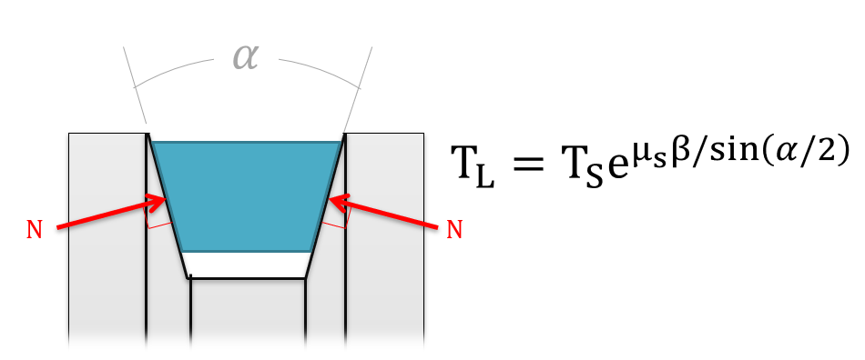
As we can see from the equation above, steeper sides to the groove (corresponding to a smaller groove angle \(\alpha\)) result in an increased potential difference in the tension forces. The trade-off with steeper sides, however, is that the belt becomes wedged more firmly in the groove and requires a higher force to unwedge itself as it leaves the pulley. This unwedging force decreases the efficiency of the belt-driven system. An alternate design choice would be a chain-driven system which carries very high-tension differences more efficiently.
Subsubsection Torque in belt systems
In belt-driven systems, there is usually an input pulley and one (or more) output pulleys. To determine the maximum torque or power that can be transmitted by the belt, we will need to consider each of the pulleys independently, understanding that slipping occurring at either the input or the output will result in a failure of the power transmission.
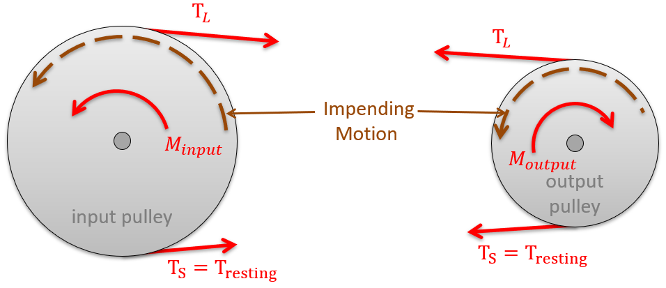
The first step in determining the maximum moment (or torque) that can be transmitted in the belt drive is to determine the maximum possible value for \(\vec{T}_\text{L}\) before slipping occurs at either the input or output pulley. To start this process, we you will need to start by solving for the resting tension. This resting tension is the tension the belts prior to anything moving or power transfer (analogous to the tension in your bike chain when it is at rest). Practically, if you wish to increase or decrease the resting tension, many machines have adjustments to increase or decrease the distance between the pulleys slightly. If we turn on the machine and increase the moments on both pulleys, the resting tension \(\vec{T}_\text{S}\) remains constant while the tension on the drive side \(\vec{T}_\text{L} \) increases.
If the pulleys are the same material (and therefore the same coefficients of friction), it can be assumed that the belt will first slip at the smaller of the two pulleys as the smaller pulley has a smaller contact angle \(\beta\text{.}\)
Once we have the maximum value for \(\vec{T}_\text{L} \) , we can use that to find the maximum input and output moments. Next, to find the torque, we then find the net moment exerted by the two tension forces, where the radius of the pulley is the moment arm.
The maximum input torque \(M_i\) before slipping is
The maximum output torque M_o before slipping is
To find the maximum power we can transfer with the belt drive system, we will use the rotational definition of power, where the power is equal to the torque times the angular velocity in radians per second. Unlike the torque, the power at the input and the output will be the same, assuming no inefficiencies.