Section 6.1 Introduction
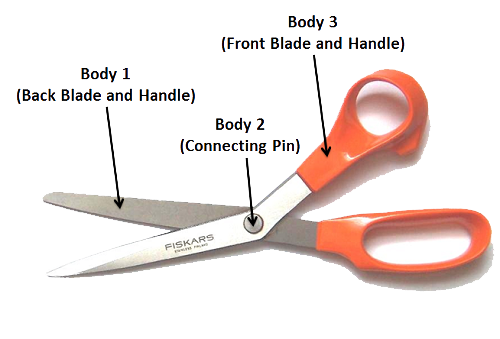
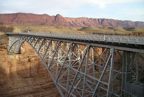
In this chapter you will conduct static analysis of multi-body structures. Broadly defined, a structure is any set of interconnected rigid bodies. The parts comprising the structure may move relative to one another, such as the blades in a pair of scissors, or they may be fixed relative to one another, such as the structural members within a bridge.
Analysis of structures involves applying the techniques you have learned in the previous chapters to solve for the forces acting on and between individual members of the structure. Fundamentally there is nothing new here, however the problems tend to have more unknown forces, and so are more involved and provide more opportunities for error than the problems you have previously encountered. Clear diagrams and careful work are required, as always.
Structures.
All structures fall into one of three broad categories: trusses, frames, and machines. A key skill you will learn in this chapter is to properly classify structures.


A truss is a multi-body structure made up of long slender members connected at their ends in triangular subunits. Truss members carry axial forces only, Trusses are commonly used for spanning large distances without interruption: bridges, roof systems, stadiums, aircraft hangers, auditoriums for example. Trusses are also used for crane booms, radio towers and the like. They are lightweight and relatively strong. Over the years many unique truss designs have been developed and are often named after the original designer.
A frame is a multi-part, rigid, stationary structure primarily designed to support some type of load. A frame contains at least one multi-force member, which a truss never has. This means that, unlike trusses, frame members must support bending moments as well shear and normal forces. Many common items can be considered frames. Some examples: building structure, furniture, ladders, scaffolding, and more.
A machine is very similar to a frame, except that it includes some moving parts. The purpose of a machine is usually to provide a mechanical advantage and multiply forces. Pliers, scissors jacks, automobile suspensions, construction equipment are all examples of machines.
Solving a structure means determining all forces acting on all the parts of the structure. The solution typically begins by determining the global equilibrium of the entire structure, then breaking it into parts and analyzing each separate part. The specific process will depend on the type of structure, but will always follow the principles covered in the previous chapters.
Two-force Members.
Identifying and analyzing two-force members will be very helpful when solving structures. Recall from Subsection 3.3.3 that a two-force body is an object subjected to exactly two forces. Two-force members are not required to be slender or straight, but usually can be recognized because they connect to other bodies or supports with two frictionless pins, and have no other loading unless it is applied at the pins.
In order for a two-force body to be in equilibrium, the forces must be 1) equal in magnitude, 2) opposite in direction, and 3) share the same line of action. If the two forces tend to stretch the object we say it is in tension. If they act the other way and squash the object, it is called compression.

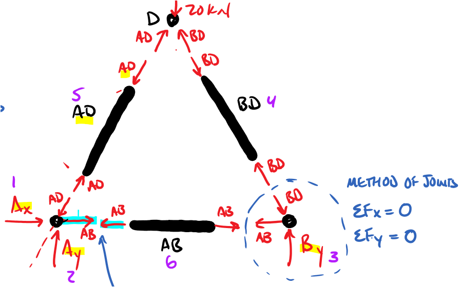
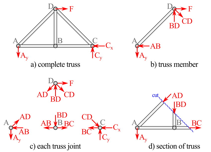
The common way to express an axial force in a two-force member is with a magnitude and a sense, where the sense is either tension or compression. For example, look at the members and joints of a truss below. Member \(AB\) is in tension, and the forces acting on it, also called \(AB\text{,}\) oppose each other and tend to stretch the member. These stretching forces are accompanied by equal and opposite forces, also called \(AB\) acting on pins \(A\) and \(B\text{.}\)
The free-body diagrams of the members can only verify that the forces on members are equal and opposite. The free-body diagrams of the joints are required to relate the forces in the members to the external reaction and applied forces.

Thinking Deeper: Equilibrium of Multi-Body Systems.
When a complete truss is in equilibrium, each member of the truss, each joint, and each section are also in equilibrium. This continues all the way down to a single atom of the structure. This universal equilibrium across spatial scales is one of the governing principles which allows us to break multi-body systems into smaller solvable parts.

You will see in this chapter that we have the freedom to isolate free-body diagrams at any scale to expose our target unknowns.
Interactions between members.
Since we are now dealing with multi-body systems, we need to recall Newton’s 3rd Law
For every action, there is an equal and opposite reaction.
This law applies to multi-body systems wherever one body connects to another. At any interaction point, forces will be transferred a body to the interacting body as an equal and opposite forces. The relation between the forces of the members on the pins, and the forces of the pins on the members shown in Figure 6.1.2 illustrate this.
When drawing free-body diagrams of the components of structures, it is critically important to represent these action-reaction pairs consistently. You may choose either direction for one, but the other must be equal and opposite.
Load Paths.
Load paths can help you think about structural systems. Load paths show conceptually how an applied load like the floor load in the image below passes through the interconnected members of a structure until it ends up at the fixed support reaction. All structural systems, whether non-moving frames or moving machines have some sort of load path. This is also a good concept to think about while problem solving, where you need to computationally move from known values through the interconnected bodies of the system, solving for unknowns as you go.