Section 9.7 Disc Friction
Key Questions
At the end of this chapter you should be able to answer these questions.
- Select the appropriate disc friction equation among those for hollow circular areas, solid areas, and disc brakes with a circular arc and
- Compute the possible moment the friction forces from disc friction can resist.
Subsection 9.7.1 Disc Friction
Disc friction is the friction that exists between a rotating body and a stationary surface. Disc friction exerts a moment on the bodies involved which resists the relative rotation of each bodies. Disc friction is applicable to a wide variety of designs including end bearings, collar bearings, disc brakes, and clutches.
Subsection 9.7.2 Collar bearing with a hollow circular contact area
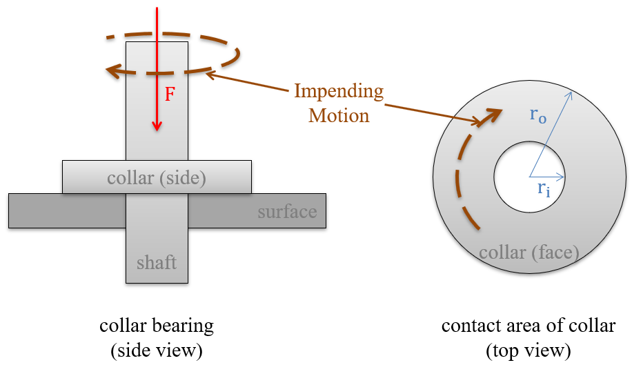
To start our analysis of disc friction we will use the example of a collar bearing, which has a hollow circular contact area between the rotating collar and the stationary surface (Figure 9.7.2). In this type of bearing, we will have a rotating shaft traveling through a hole in a surface. The shaft is supporting some load force as shown and a collar is used to support the shaft itself.
The friction force at any point in the contact area will be equal to the normal force at that point times the kinetic coefficient of friction at that point. If we assume a uniform pressure between the collar and the surface and a uniform coefficient of friction, then we will have the same friction force exerted at all points. This does not translate however into an equal moment exerted by each point. Points further from the center of rotation will exert a larger moment than points closer to the center of rotation because they will have a larger moment arm.
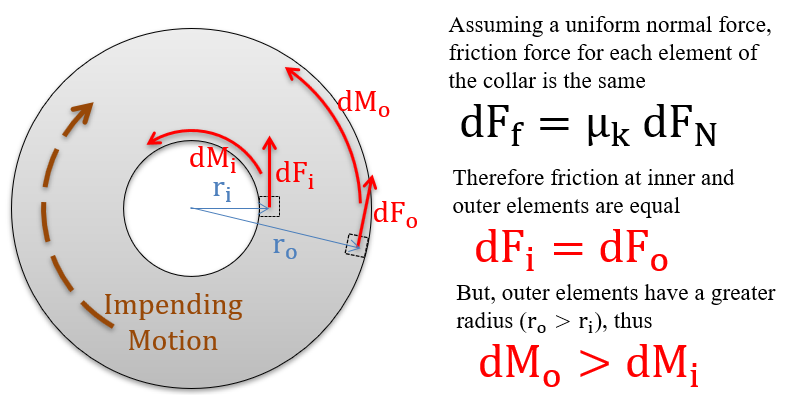
To determine the total moment exerted by the friction forces, we will need to integrate the friction from all elements of the contact area. The moment of each element (\(dM\)) will be equal to the product of the kinetic coefficient of friction (\(\mu_k\)), the normal force pressure (\(p\)), the distance from that point to the center of rotation (\(r\)), and the area of each element (\(dA\)).
The total friction moment can be found by integrating the moment of each element over the contact area:
To simplify the equation we can move the constant coefficient of friction and the constant normal force pressure term outside of the integral. We can also replace the pressure term with the applied force on the bearing over the contact area. Finally, so that we can integrate over the range of \(R\) values, we can recognize that the rate of change in the area (\(dA\)) for the hollow circular areas is simply the rate of change of the \(r\;dr\) term time the circumference of the circle at \(r\text{.}\) These changes lead to the equation below.
Finally, we can evaluate the integral from the inner radius to the outer radius. If we evaluate the integral and simplify we will end up with the final equation below.
Subsection 9.7.3 End bearing with a solid circular contact area
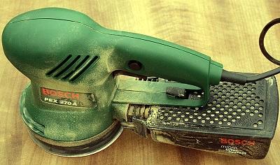
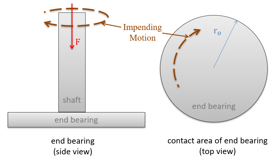
In cases where we have a solid circular contact area such as with a solid circular shaft in an end bearing or with the orbital sander shown at the top of the page we simply set the inner radius to zero and we can simplify the formula. If we do so, the original formula is reduced to the equation below.
Subsection 9.7.4 Disc brakes with a circular arc
Disc brakes have a contact area that looks like a section of the hollow circular contact area we covered earlier.
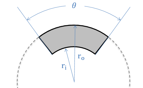
However, disc brakes, due to their smaller contact area, have both smaller area over which to exert friction force and also higher pressure for the same applied force. In the end, these factors cancel each other out and we end up with the same formula we had for the hollow circular contact area (independent of \(\theta\)).
Brake pad on one side:
Most disc brakes, however, have a pair of pads (one on each side of the rotating disc), so we will need to double the moment in our equation for the usual pair of pads.
Brake pads on each side: