Section 9.6 Journal Bearing Friction
Key Questions
At the end of this chapter you should be able to answer these questions.
- Draw a problem sketch and FBD of a journal bearing system including the appropriate shift in contact point due to impending rotation
- Solve for unknown values associated with journal bearing
Subsection 9.6.1 Journal Bearing Friction
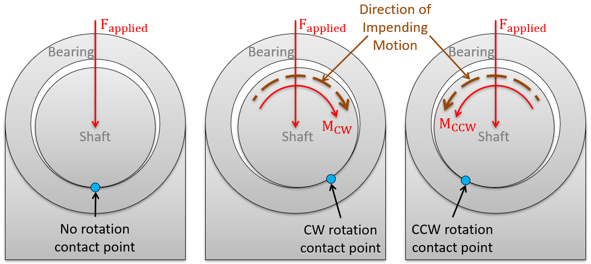
A bearing is a machine element used to support a rotating shaft. Bearing friction is the friction that exists between the rotating shaft and the supporting bearing. Though many types of bearings exist (journal, ball, roller, hydrodynamic), in this course, we only focus on dry friction journal bearings. Most bearings are lubricated and thus require knowledge of fluids to analyze, but dry friction journal bearings have a single contact point between the shaft and bearing (as shown in Figure 9.6.1 below). While the single contact point makes them solvable in statics, the single contact point would be subject to wear and heat build-up if used for long-duration motion; thus, the use of journal bearings is only advisable in situations where there is limited motion.
Subsection 9.6.2 Journal bearings with a rotating shaft and a fixed bearing
A journal bearing consists of a circular shaft fitted into a slightly larger circular bearing, as shown in Figure 9.6.1. The application of a standard journal bearing includes a rotating shaft, which is also exerting a load \(F_\text{load}\) onto the bearing. The friction force and shaft rotation cause the shaft to climb up the side of the bearing.

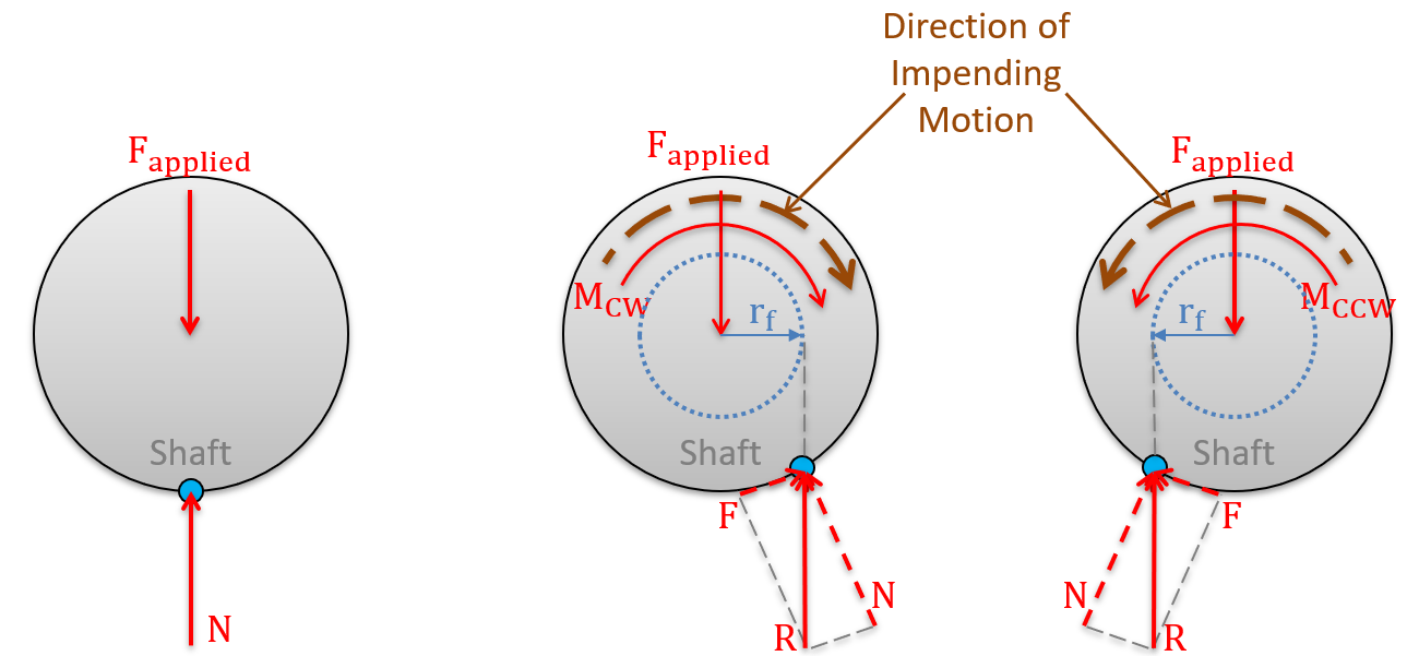
Now that you have learned the underlying physical interaction between a shaft and journal bearing, let us transition to the forces which support this interaction. If we create FBDs s for the shaft in all three cases presented in Figure 9.6.1 above, we see a combination of a normal force \(\vec{N}\) and a friction force \(\vec{F}\) at each contact point (in Figure 9.6.2 below).

The most straightforward process to accurately relate the normal and friction forces for a journal bearing is by performing the following steps:
- First, assume for measured distances that the shaft and bearing opening have the same radius, but always draw the shaft a bit smaller so you can see its contact point with the bearing. Drawing them the same size will make it look like the shaft and bearing are in contact all the way around, which would violate our assumption of a single point of contact.
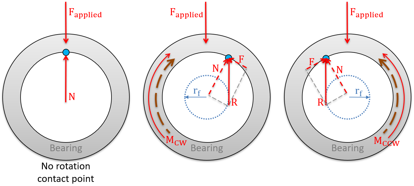
- Next, combine the normal and friction forces into a single friction resultant force (as presented in the first section of this chapter)\begin{equation*} \vec{R}=\vec{F}+\vec{N}\text{.} \end{equation*}
- The friction resultant can then be assumed to be tangential to a “friction circle.” The friction circle is an imaginary circle of radius \(r_f\) around the center of the shaft and is a function of the radius of the shaft (r) and the friction angle \(\phi_s\text{.}\)\begin{equation*} r_f=r \sin \phi_\text{s} \text{ where, } \phi_\text{s} =\tan^{-1} \mu_\text{s} \end{equation*}
- Finally, draw your FBD of the shaft (and/or bearing) with all applied loads and the friction resultant \(\vec{R}\) and then use your equations of equilibrium to solve the problem.
Subsection 9.6.3 Journal bearings with a fixed shaft and a rotating bearing
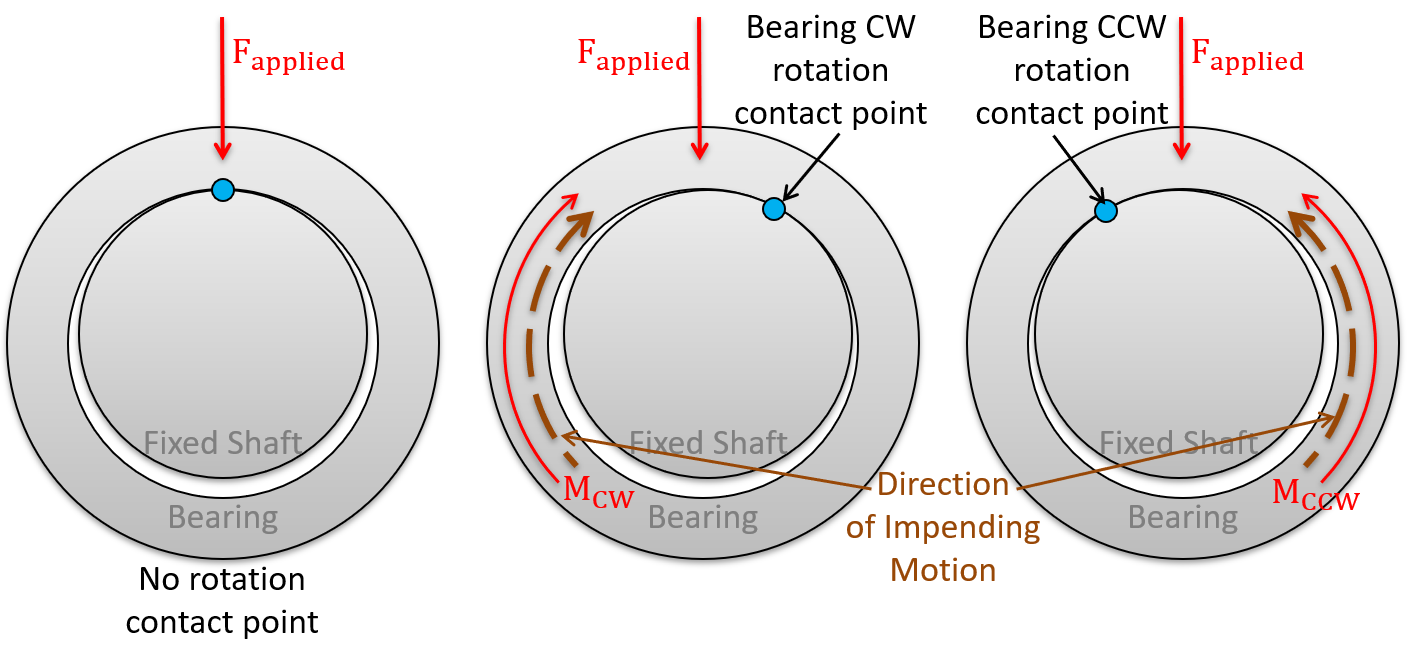
Another type of journal bearing is designed with a fixed shaft and a rotating bearing. While the solution process is quite similar to the process covered above, the main difference is that you will draw an FBD of the rotating bearing (instead of the shaft) for this case.


Application Box: Finding the direction of shift for contact point.
If you are still struggling to determine the direction of the contact point shift, try this rule:
The contact point always shifts in the direction of the impending motion of the bearing.
The impending motion can be absolute (in the case of a fixed shaft and rotating bearing) or relative (in the case of a fixed bearing). Remember, the relative motion of the bearing is always opposite the absolute impending motion of the shaft.