Section 9.2 Block and Wedge Friction
Key Questions
At the end of this chapter you should be able to answer these questions.
- Show on a free-body diagram how a normal force always remains perpendicular to the contact surface, while the friction force lies parallel to the contact surface
- Demonstrate graphically that components of friction and normal forces are related to the right-triangle trigonometry terms sine and cosine.
In this section, a block is defined as any rectangular rigid body. A wedge is a tapered object that forces objects apart or holds something in place. Wedges are used in two primary ways:
Low friction wedges are a simple machine which allows users to create large normal forces to move objects with comparatively small input forces.
High-friction (self-locking) wedges control the location of or hold things in place (as in doorstop wedges or carpentry wedges).

Luckily the free-body diagrams and computations associated with both low- and high-friction wedges are identical. Block and wedge friction problems are quite similar to the multi-force body equilibrium problems from Chapter 5 Rigid Body Equilibrium and Chapter 6 in the Frames and Machines section. The main difference is the inclusion of friction from all non-smooth contact surfaces. The directions of both the normal and friction forces on the free-body diagrams are defined below.
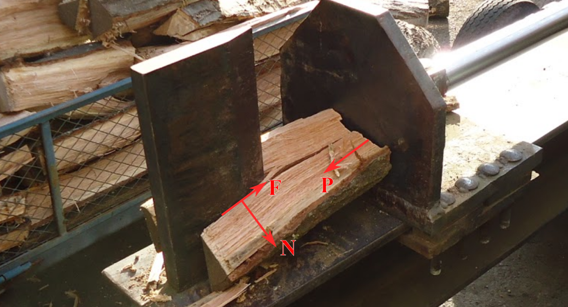
Normal forces act between bodies are reactions forces perpendicular to the contacting surfaces. All normal forces on a FBD should be pointing at (and not away from) the body.
Friction forces are reaction forces between bodies parallel (or tangential) to the contacting surfaces and created by the roughness of both surfaces. All friction forces on an FBD should resist the motion at the point of contact.
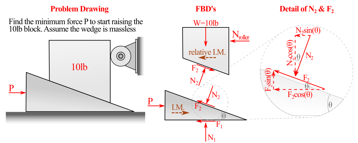
The key added challenge of solving wedge problems is that the angled faces of wedges create additional force components in your equations. One of the critical steps to solve a block or wedge problem is to look at the problem statement and drawing to determine which force is engaging the friction of the system. Start by drawing the friction forces on the body where this force acts (see Figure 9.2.2). As you are passing the friction and normal forces to adjacent FBDs, do not forget to draw both friction and normal forces in the opposite direction.

If the problem in Figure 9.2.2 was changed to “Given a coefficient of static friction of \(\mu_\text{s}=0.6\) find the minimum force \(P_2\) to keep the wedge from slipping out under the \(\lb{10}\) block”, the FBDs would need to change in the following ways:
- all friction force directions would change as the impending motion of both the wedge and \(\lb{10}\) block would change direction and
- the direction of \(P\) may have to change if the wedge has sufficient friction to stay static when \(P=0\text{.}\)
Note that for all values of \(P\) between \(P_1\) and \(P_2\) the system would be static, and the friction forces would be static-but-not-impending.